Approximately Up Gyro Line Guide: How It Works & Wiring
What the Gyro Line does in Approximately Up: pitch and roll attitude readout, how to power and wire it, and the auto-leveling circuit (checked Aug 13, 2026).
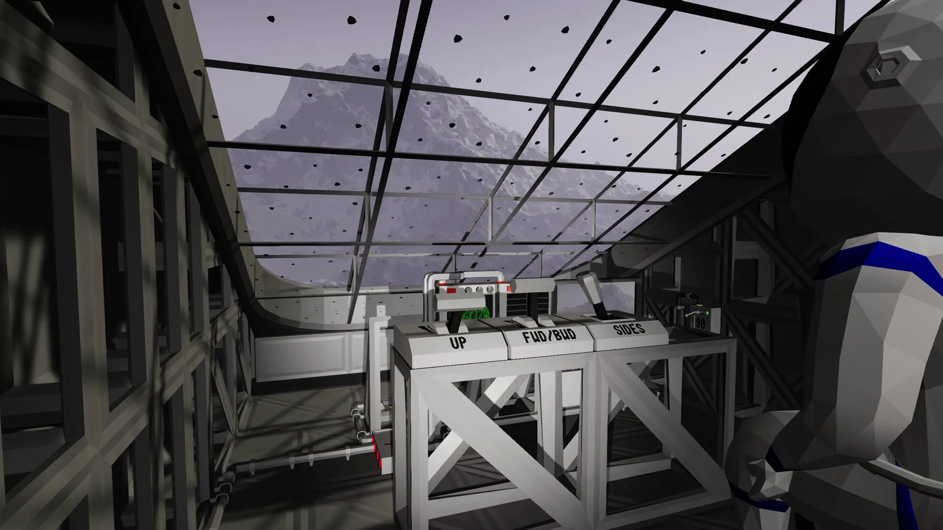
The Gyro Line is the attitude instrument of Approximately Up: it measures your ship’s tilt and reports pitch and roll as signed values in degrees. Unlike the altimeter, which is data-only, the Gyro Line needs power before it will show anything, so a blank readout is usually a power problem. Players mount it as a cockpit attitude readout, and its data output can be chained onward to monitors. If you want to know whether your ship is flying level — or to build a ship that levels itself — this is the part you wire first.
Version note: instrument behavior on this page was checked on August 13, 2026 against patch 1.0.010, the latest confirmed release note. Several wiring details come from demo-era tutorials and are marked (demo-era).
What Is the Gyro Line?
The Gyro Line is an instrument that measures your ship’s attitude — how much the ship is tilted — and reports pitch and roll as signed values in degrees, so the sign tells you the direction of the tilt and not just the amount. It became the community’s go-to after the inclinometer and rotometer misbehaved: those parts once always output positive values, which made self-stabilizing builds impossible. The developer fixed the Axis Rotometer in patches — 1.0.006 added signed output and 1.0.008 fixed its hitbox — but discussion threads still point players at the Gyro Line as the reliable alternative.
The part’s wiring traits come from demo-era tutorials and match what players report after launch: it needs power, it shows pitch/roll level, and its data output can be chained to monitors (demo-era). For context, the inclinometer’s own game-text description measures the difference in degrees between the component’s down direction and the gravity direction (demo-era). The manual includes an RCS wiring diagram, so the Gyro Line usually sits next to the RCS controller in builds (demo-era). For the full part catalog, see parts-and-instruments; for gates, dividers and cable rules, see circuits-and-logic.
What It Shows
On the ship, the Gyro Line gives a live attitude readout: pitch tilt and roll tilt in degrees (demo-era tutorial wording). Players use it two ways: as a dashboard instrument while flying, and as a sensor input for automation, because the degree values are also data signals you can feed into logic. The same demo tutorial chains the Gyro Line’s data output to monitors, so the readout can live anywhere a monitor sits (demo-era). The gravity meter, a separate instrument that unlocks later in the game, covers the gravity number pilots also watch (player-reported, release).
It is one member of a flight-instrument family players wire together. The velocity meter supports directional and overall modes — use overall for interplanetary travel (player-reported, release). The altimeter measures height above sea level, is data-only with no power port, and must sit outside with an unobstructed view — the common mounting advice is blue face down on the ship’s bottom, though some players report top mounting working too. The Gyro Line’s own readings are signed, which is exactly what makes it usable as a stabilizer input where the rotometer used to fail.
Patch 1.0.100 highlighted the middle line of the Gyro-Line so the center of the screen is easier to see during attitude flying (official Steam news, August 21, 2026).
How to Wire It
Power comes first: run a power cable from your battery circuit into the Gyro Line’s red port, because an unpowered Gyro Line shows nothing. Demo-era port colors help: red = power, yellow = data input, blue = data output (mnemonic: yellow hello, blue adieu) (demo-era). The blue data output then carries the pitch/roll signal onward — to monitors for a cockpit readout, or into logic gates for automation.
Like every cable in the game, the Gyro Line’s cables must attach to solid surfaces — frames or walls — or the run snaps; unsupported spans of roughly 5 to 8 tiles break, so route the wires along your frame. Build mode’s H key highlights unsupported and unconnected wires in red so you can catch bad runs before Fly Mode. The in-game manual, opened with M, includes wiring diagrams if you want the reference while soldering (demo-era), and in the release build you can also open the manual from a seat, a convenience patch 1.0.008 added (official).
Using It in an Auto-Leveling Circuit
OwtSpectre’s “useful systems to have in the ships you build” tutorial builds a full auto-leveling system around the Gyro Line (demo-era). The recipe: take the Gyro Line’s pitch and roll outputs (in degrees), feed each through a division gate that divides by -30 — the negative sign flips the correction direction, and 30 keeps the correction slow — then add the result to the joystick 3D pitch and roll signals with addition gates. The Gyro Line and the RCS controller both need power for the loop to run, and you set the divisor by looking at the gate and pressing E.
In that same demo setup, after the final mission the small maneuvering thrusters wire through wireless transmitters instead of the RCS controller (demo-era). The whole recipe is demo-era, so treat it as the proven starting point rather than a release-patch guarantee: whether the current build’s Gyro Line behaves identically is not yet confirmed in official sources. If you are flying out to the planet Aundara (also spelled Aandara), the Gyro Line is the instrument that gives you a numeric readout of the 45-degree roll used in the Jight route — see aundara.
Common Issues
- Blank readout: check power first. The Gyro Line needs power, and a missing power cable is the classic dead-instrument cause (demo-era tutorial, matching player reports).
- Self-stabilizing with the inclinometer or rotometer: those once only output positive values, so the loop could not correct both directions. Use the Gyro Line’s signed output instead; 1.0.006 added signed output to the Axis Rotometer and 1.0.008 fixed its hitbox (official).
- Auto-level oscillating or over-correcting: raise the divisor — 30 is the demo tutorial’s slow-and-steady value (demo-era).
- Correction pushing the wrong way: make the divisor negative to flip the direction (demo-era).
- Manual control fighting the loop: sum the correction with the joystick signal through addition gates, so your stick input still wins (demo-era).
- Cables snapping near the instrument: route along solid surfaces and press H in build mode to see red unsupported runs.
Sources
Verified August 13, 2026.
- Steam store page: https://store.steampowered.com/app/3904850/Approximately_Up/ (official — instruments, wiring and automation)
- Steam News: https://steamcommunity.com/games/3904850/announcements/detail/1840310314344927 (1.0.006 Axis Rotometer signed output), https://steamcommunity.com/games/3904850/announcements/detail/1840310314351624 (1.0.008 Axis Rotometer hitbox)
- Steam discussions (player reports): https://steamcommunity.com/app/3904850/discussions/0/588434161796217817/ (inclinometer and rotometer, Gyro Line alternative), https://steamcommunity.com/app/3904850/discussions/0/845132006378512954/ (altimeter mounting), https://steamcommunity.com/app/3904850/discussions/0/592937694876678114/ (wire snapping rules)
- YouTube (community tutorials): https://www.youtube.com/watch?v=FXF1UfYqagY (Diggrok build tutorial, demo-era), https://www.youtube.com/watch?v=xElHhIEW10k (OwtSpectre systems tutorial, demo-era), https://www.youtube.com/watch?v=EPaH2IL3sNo (SaNT xc livestream, release)
- Images: official Steam news headers and official Steam store screenshots for Approximately Up.
Fan-made guide. This site is not affiliated with Approximately Games, Steam, or Valve; all game content and media belong to their respective owners. Factual details were last checked on August 13, 2026.